
On this page
Start here
Quick answer
Loose, misidentified, or incorrectly configured ecobee control wiring can make an HVAC system respond to the wrong call or lose the call, but short cycling is not proof of a wiring fault. First record whether the ecobee still shows an active heat or cool call, then turn HVAC power off before making a visual check of the thermostat terminals and any recent installation work. Compare the visible labels with the exact ecobee wiring diagram and equipment setup; do not move wires, open the HVAC control cabinet, or test live circuits unless a qualified technician is doing it. If rapid cycling continues after the wiring configuration is confirmed, or if there is a loose connection, blank display, error, burning smell, exposed wiring, or repeated breaker trip, stop and arrange qualified HVAC service.
Before you begin
Safety first
- Do not move wires, open the HVAC control cabinet, test energized circuits, measure refrigerant or electrical values, bypass controls, or restart after smoke, burning odor, exposed wiring, arcing, water near electrical parts, or repeated breaker trips.
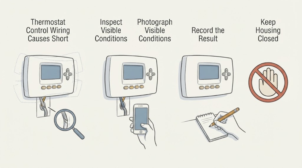
Work through in order
Diagnostic checks
Use only checks that match the exact appliance or system and its official guide.
-
Check 1
Observe one normal heat or cool call without repeatedly changing the setpoint. Record the ecobee mode, whether the display says the equipment is running, whether the indoor fan and outdoor unit start together, when each stops, and whether the thermostat call remains visible during the stop.
Expected result: The ecobee call disappears or changes unexpectedly, the call remains while equipment stops, the display is blank or shows an alert, or the equipment and thermostat start and stop together.
Next step: Use the matching branch below. Do not keep forcing starts or repeatedly resetting the thermostat while the cause is unknown.
Why this matters
Why: A disappearing or changing call makes a thermostat setting, configuration, connection, or power issue more plausible. A persistent call with equipment stopping points more toward the HVAC equipment, a protective control, or a fault elsewhere. A blank display or alert is a power or diagnostic branch, not proof of a wiring defect.
-
Check 2
If wiring was recently installed or changed, turn off power to the HVAC system at the documented switch or breaker before touching the thermostat faceplate. Photograph the visible terminal labels and wires exactly as they are, and check only whether each conductor appears fully seated and the terminal lever or screw is not visibly open; do not disconnect or move a wire.
Expected result: A wire is visibly loose, not seated, pulled out, or unlabeled; the wire insulation is damaged; or all visible connections appear secure and unchanged.
Next step: Leave a questionable connection untouched and arrange qualified HVAC service. If every visible connection is secure, continue with model-specific configuration and system checks rather than moving wires yourself.
Why this matters
Why: A loose or damaged visible connection can interrupt a control call, but terminal appearance alone cannot confirm a safe repair or the correct function. A secure-looking thermostat connection shifts attention to the equipment-side connection, configuration, or another short-cycling cause.
-
Check 3
Compare the photographed thermostat terminal labels with the exact ecobee installation guide for the thermostat model and the home's system type. Check whether the system is conventional, a heat pump, or a heat pump with auxiliary heat, and whether a Power Extender Kit is part of the installation; do not apply a diagram from another model.
Expected result: The installed terminal pattern matches the exact model and equipment type, or the diagram, heat-pump selection, auxiliary-heat selection, O/B function, R terminal arrangement, or Power Extender Kit path does not match.
Next step: Do not rewire from an internet diagram. Save the photos and exact model information for ecobee support or a qualified HVAC technician to verify and correct the configuration with power isolated.
Why this matters
Why: A mismatch can cause incorrect calls or missing equipment operation, especially when a heat-pump diagram is confused with a conventional diagram or when a Power Extender Kit is wired for a different path. A matching diagram reduces the chance that a visible thermostat-label mismatch is the cause but does not rule out a hidden connection or equipment fault.
-
Check 4
Review the ecobee equipment settings and recent installation history without changing advanced wiring options: selected heat-pump or conventional equipment, number of stages, auxiliary heat, reversing-valve setting, fan control, and any configuration or installation alert. Record what the app or thermostat reports rather than guessing from wire colors.
Expected result: The ecobee equipment type or stages do not match the actual system, a configuration alert is present, the settings are correct, or the settings are unknown because the installation was inherited or recently changed.
Next step: Use the exact ecobee model guide or have a qualified technician verify the settings against the equipment. Do not change O/B, auxiliary-heat, staging, or control parameters merely to make a cycle start.
Why this matters
Why: A configuration mismatch can produce the wrong control sequence even when a wire is physically secure. Correct-looking settings with persistent short cycling leave wiring, the HVAC equipment, protective controls, and other causes unresolved.
-
Check 5
Check only safe external conditions that can make a correctly wired system appear to short cycle: the air filter is clean and correctly installed, visible supply and return openings are open, and the outdoor unit is free of loose debris. Look for thick ice, weak airflow, water, unusual noise, or a breaker that trips again; do not open equipment panels.
Expected result: Airflow is restricted, ice or water is present, the outdoor unit is blocked, or the external conditions are normal while the ecobee continues to show an active call during each stop.
Next step: Correct only a visible loose obstruction or the model-correct filter. Stop for ice, water near electrical parts, burning smell, exposed wiring, or repeated trips; arrange qualified HVAC service for a persistent symptom.
Why this matters
Why: Airflow and coil conditions can trigger protective operation and mimic a wiring fault. Normal external conditions with a persistent active call make professional checks of controls, wiring at the equipment, refrigerant, compressor, fan, and sizing more important.
-
Check 6
Prepare a service record instead of repeated resets: ecobee model, HVAC equipment type, terminal photo, whether a C wire or Power Extender Kit is used, recent installation or wiring changes, thermostat call state during each stop, configuration alerts, filter and airflow observations, ice or water, and breaker behavior.
Expected result: The symptom started immediately after ecobee installation or wiring work, improves only when the thermostat is removed from the call, returns with the same configuration, or has no clear relationship to a recent change.
Next step: Give the complete record to ecobee support or a qualified HVAC technician. Have them verify the exact diagram, terminal continuity, equipment-side connections, protection settings, and system operation; do not perform live electrical tests yourself.
Why this matters
Why: A close timing relationship raises the priority of verifying the ecobee wiring and setup, but it still does not prove which conductor or control is faulty. No recent change or an active call through the stop makes an HVAC-side diagnosis equally important.
Use your observations
Decision map
Find the observation that best matches what you see, then follow the next safe action.
-
PATH 01Next step
What you see
The ecobee call disappears, changes mode, or shows an alert while the system is short cycling, especially after wiring or configuration work.
Do this next
Leave the wiring untouched, save the terminal photo and alert text, and have ecobee support or a qualified HVAC technician verify the model-specific wiring and equipment setup with power isolated.
Why this path and its safety boundary
Why it matters: A thermostat power, terminal, configuration, or control-path issue is more plausible than a simple equipment response, but the exact wire cannot be identified from the symptom.
-
PATH 02Next step
What you see
The thermostat call remains active while the outdoor or indoor equipment stops, and the visible wiring and settings match the exact ecobee diagram.
Do this next
Stop repeated restart tests and arrange qualified HVAC diagnosis. Do not open the equipment, measure a circuit, or bypass a safety control.
Why this path and its safety boundary
Why it matters: The ecobee is continuing to request operation, so a protective control, airflow, coil, refrigerant, compressor, fan, equipment-side connection, or sizing issue becomes more likely than a simple thermostat terminal mismatch.
-
PATH 03Next step
What you see
A wire is visibly loose, damaged, or not seated, or the equipment type, stage count, reversing-valve setting, or Power Extender Kit path does not match the exact ecobee instructions.
Do this next
Do not move or reconnect the conductor yourself. Keep the HVAC system off if the connection is exposed or unstable and arrange professional verification of the wiring and configuration.
Why this path and its safety boundary
Why it matters: The installation or control wiring may be unable to deliver the intended call, but a visible mismatch does not establish which repair is safe.
-
PATH 04Next step
What you see
The wiring and configuration match, but the filter is restricted, registers are blocked, the outdoor unit is obstructed, or the coil is icing.
Do this next
Correct only the model-correct filter or a loose visible obstruction. Do not chip ice or open panels; persistent ice, weak airflow, or recurring cycling needs qualified service.
Why this path and its safety boundary
Why it matters: Airflow or coil conditions can produce protective cycling and make the thermostat appear responsible even when its call is correct.
-
PATH 05Next step
What you see
The ecobee display, wiring, configuration, filter, and external airflow look normal, but rapid cycling continues or returns after one supervised call.
Do this next
Arrange qualified HVAC diagnosis and provide the service record. Do not keep changing advanced ecobee settings or resetting the system to force operation.
Why this path and its safety boundary
Why it matters: The issue is not explained by the safe homeowner checks. An equipment-side control, refrigerant, compressor, fan, defrost, or sizing fault remains possible.
-
PATH 06Next step
What you see
There is smoke, burning odor, exposed or frayed wiring, arcing, water near electrical parts, a persistent error, or a repeated breaker trip.
Do this next
Stop immediately, keep clear, isolate power only from a safe dry location if necessary, and arrange qualified or emergency help. Do not restart or bypass the control.
Why this path and its safety boundary
Why it matters: This is a safety stop beyond thermostat troubleshooting and may involve electrical, water, or HVAC equipment hazards.
Helpful context
Understand the symptom
What a wiring-related short-cycle pattern looks like
Watch the ecobee display at the same time as the equipment. If the thermostat still shows an active call while the outdoor or indoor equipment stops, the HVAC side or a protective control may be interrupting operation. If the call disappears, reappears, or does not match the selected mode, a thermostat setting, terminal connection, configuration, or low-voltage control path becomes more plausible. That observation narrows the next step; it does not identify a wire or component by itself.
Use the exact ecobee diagram
ecobee diagrams differ by equipment type and installation method. A heat pump with auxiliary heat uses terminals and functions that are not interchangeable with every conventional setup, and a Power Extender Kit changes the wiring path. Do not copy a terminal arrangement from a different ecobee model, heat-pump type, or online image. Use the model's installation flow or have a professional verify the system.
Safety boundary
Stop conditions
- Do not move or jumper thermostat conductors, open the HVAC control cabinet, test live wiring, measure refrigerant or electrical values, bypass a safety control, or copy a terminal arrangement from another ecobee model.
- Stop immediately for smoke, burning odor, exposed or frayed wiring, arcing, water near electrical parts, a persistent error, or repeated breaker trips. Keep clear and arrange qualified help.
- If a visible connection is loose or damaged, leave it untouched and arrange service. If the wiring appears correct but short cycling persists, stop repeated restart tests and have the thermostat and HVAC equipment evaluated together.
Only after diagnosis
Potential parts
- ecobee thermostat or compatible backplate
Consider only after qualified diagnosis confirms the thermostat or its connection interface is faulty and the equipment compatibility and wiring are verified.
ecobee models, backplates, terminals, and supported HVAC systems differ. Confirm the exact model and system type before selecting a replacement. - ecobee Power Extender Kit
Consider only when the exact ecobee installation method requires a Power Extender Kit and qualified diagnosis confirms the existing kit or its wiring path is defective.
PEK use depends on the thermostat model, available conductors, and HVAC control-board arrangement. Confirm the exact diagram and installation method first. - thermostat control wire or HVAC control component
Consider only after qualified service confirms a damaged conductor, terminal, control board, relay, or other equipment-side fault causing the verified short-cycle pattern.
Control wiring and HVAC components are system-specific and may involve high-voltage equipment. Use professional diagnosis and exact model fitment information.
When checks do not resolve it
Need a professional?
Arrange qualified HVAC service when ecobee short cycling persists after safe observation and external checks, when a thermostat wire is loose or damaged, when the wiring or Power Extender Kit does not match the exact ecobee diagram, or when configuration, equipment-side wiring, airflow, coil, refrigerant, compressor, fan, defrost, or sizing trouble is suspected. Treat smoke, burning odor, exposed wiring, arcing, water near electrical parts, persistent errors, and repeated breaker trips as immediate safety stops.
Safety scope: Do not move wires, open the HVAC control cabinet, test energized circuits, measure refrigerant or electrical values, bypass controls, or restart after smoke, burning odor, exposed wiring, arcing, water near electrical parts, or repeated breaker trips.
Common questions
FAQ
Can ecobee control wiring cause short cycling?
It can contribute if a conductor is loose, misidentified, or configured for the wrong equipment type, but the symptom is not proof of a wiring fault. Compare the visible labels and equipment setup with the exact ecobee diagram, then have a professional verify any mismatch or required rewiring.
What can I safely inspect on an ecobee thermostat?
You can observe the mode and equipment-call status, record the model and recent changes, and after HVAC power is safely off look for an obviously loose or damaged visible thermostat connection without moving it. Do not open the HVAC control cabinet, move conductors, or test live circuits.
Does an ecobee wiring diagram apply to every heat pump?
No. ecobee provides model- and system-specific diagrams, including different paths for heat pumps with auxiliary heat and for a Power Extender Kit. Use the exact thermostat and equipment instructions rather than copying another diagram.
What if the ecobee call stays on while the heat pump stops?
That pattern means the thermostat may still be requesting operation, so an equipment-side connection, protective control, airflow, coil, refrigerant, compressor, fan, or sizing issue is possible. Stop repeated restart tests and arrange qualified HVAC diagnosis.
When should I stop troubleshooting ecobee wiring?
Stop for exposed or frayed wiring, smoke, burning odor, arcing, water near electrical parts, a persistent error, or repeated breaker trips. Also stop if the wiring appears loose or a panel must be opened; keep clear and arrange qualified HVAC service.
Read the exact guide
Official sources
- Thermostat compatibility checkerecobee · ecobee's compatibility checker for matching a thermostat to a home's heating and cooling system.
- How to install ecobee3 liteecobee · ecobee3 lite installation guide; terminal layout and Power Extender Kit details are model-specific.
- Common Thermostat Issues and How to TroubleshootCarrier · General residential HVAC troubleshooting context for distinguishing wiring, thermostat, airflow, and equipment causes; the ecobee model guide controls ecobee-specific wiring.
- ecobee API | Settings Objectecobee · ecobee settings reference; API fields describe available thermostat settings and do not replace the exact installation guide.
- What Is AC Short Cycling: Causes, Effects, and TroubleshootingCarrier · General HVAC short-cycling mechanism and differential causes; used to avoid attributing every short cycle to ecobee wiring.
- WIRING DIAGRAM Heat pump (air or geothermal) with auxiliary heatecobee · ecobee3 lite heat-pump air or geothermal system with auxiliary heat; other ecobee models and equipment can differ.
- Installing your SmartThermostat Premiumecobee · SmartThermostat Premium installation; wiring and PEK details vary by ecobee model and HVAC system.
Community feedback
Share a repair observation
Share a plain-text repair observation. Accepted observations are published automatically; this page may take a moment to update.