
On this page
Start here
Quick answer
Do not assume thermostat control wiring is the cause of short cycling. First log whether the system starts and stops on its own schedule, whether the thermostat display or power changes, and whether the fan, heat, or cooling call ends with an airflow or equipment warning. Check only user settings, batteries if fitted, the accessible filter, and visible wire or wall damage without removing the thermostat or touching terminals. Turn the HVAC system off at its normal control before any external visual check; never measure live voltage, jumper terminals, open the equipment, or alter wiring. Persistent short cycling needs an HVAC professional to separate thermostat timing or settings from restricted airflow, a high-limit or coil protection shutdown, equipment sizing, control-board faults, or a loose low-voltage connection.
Before you begin
Safety first
- The technician separates thermostat settings and power from low-voltage wiring, equipment protection, airflow, sizing, controls, and sensor causes, then confirms compatibility before selecting a thermostat, sensor, or wire kit.
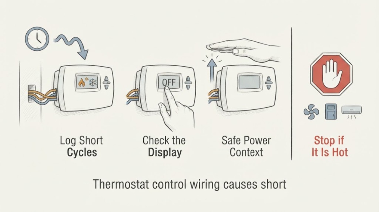
Work through in order
Diagnostic checks
Use only checks that match the exact appliance or system and its official guide.
-
Check 1
From a normal standing position, make a short log of the thermostat mode, setpoint, time a heating or cooling call starts, time it stops, whether the fan continues, and whether the system restarts without a new command. Do not repeatedly force calls just to collect entries.
Expected result: The system may stop at a planned setpoint, stop early and restart, show a call while equipment is off, or cycle with no stable pattern.
Next step: Keep the log and continue with display, settings, and airflow observations; stop using the system if it produces smoke, gas odor, unusual heat, water, or a safety alarm.
Stop if: Stop immediately for smoke, gas odor, carbon-monoxide alarm, sparking, burning smell, water at electrical equipment, or unsafe equipment behavior.
Why this matters
Why: Timing separates a normal command or schedule change from a short-cycle pattern, but it does not identify control wiring as the cause.
-
Check 2
Use only the thermostat's normal screen and buttons to record mode, schedule or hold, setpoint, fan setting, battery or power indication, error message, display resets, and the displayed room temperature. Do not remove the faceplate, alter installer settings, or use a jumper.
Expected result: The display may be stable and accurate-looking, show a schedule or hold that explains the call, reboot or go blank, show an alert, or disagree with room conditions.
Next step: Photograph the screen and exact wording, restore only an obvious user-level schedule or mode if the manual permits, and do not change wiring or hidden settings.
Stop if: Do not open the thermostat, bridge terminals, probe contacts, or continue if the display is hot, cracked, wet, sparking, or repeatedly losing power.
Why this matters
Why: A stable screen with an unexpected schedule differs from a power or wiring symptom; a blank, resetting, or persistent alert requires professional control diagnosis.
-
Check 3
If the display is blank or resets, check whether the HVAC service switch or labeled breaker is visibly off or tripped from a dry, safe position; do not repeatedly reset it. Note whether other equipment or the thermostat loses power at the same time.
Expected result: Power may be present and stable, a breaker or service switch may be off, the display may recover and then fail again, or the cause may be unclear.
Next step: Leave a repeatedly tripping circuit off and call qualified service; do not remove panels, touch wiring, or test for voltage.
Stop if: Stop for a hot panel, smoke, sparks, shock, water, exposed conductors, or any need to access energized equipment.
Why this matters
Why: A power interruption or unstable display changes the path away from a simple timing setting; a repeat trip or recurring reset needs electrical and HVAC diagnosis.
-
Check 4
With the HVAC system off at its normal control, inspect only the accessible air filter, supply and return grilles, and visible condensate or equipment-area moisture from a safe position. Note weak airflow, blocked grilles, a visibly loaded filter, ice, water, unusual heat, or a service indicator; do not open the furnace, coil cabinet, or heat-pump housing.
Expected result: Airflow may be normal, restricted at a grille, reduced with a loaded filter, or accompanied by ice, water, a limit or fault indication, or unusual heat.
Next step: Replace a user-accessible filter only when the exact equipment instructions permit it, then stop repeated operation and arrange HVAC service if cycling persists or any equipment warning is present.
Stop if: Do not open equipment panels, touch refrigerant or combustion parts, use live instruments, or operate equipment with ice, water, smoke, or abnormal heat.
Why this matters
Why: Carrier identifies restricted airflow, frozen coils, safety switches, and equipment faults as possible short-cycle causes; these findings do not prove a thermostat wire fault.
-
Check 5
After the HVAC system is off, look from the outside at the thermostat wall plate, cable entry, and any wire visible without moving the thermostat. Record a pulled-away plate, pinched or cut insulation, recent paint or remodel work, moisture, or a wire that is no longer where it was; do not pull, strip, reconnect, or remove a conductor.
Expected result: The exterior may look unchanged, show visible cable or mounting damage, show moisture, or be impossible to assess without opening the thermostat or equipment.
Next step: Photograph the visible context and provide it with the cycle log; keep the thermostat and wiring untouched until service diagnoses the circuit.
Stop if: Stop for exposed copper, water, heat, smoke, a loose thermostat falling from the wall, or any need to remove the cover or touch terminals.
Why this matters
Why: A visible change raises the priority of a professional low-voltage inspection, while an intact exterior does not clear a hidden loose connection or control fault.
-
Check 6
Record the thermostat and HVAC model labels that are already accessible, system type shown on the user screen or manual, whether the system is single- or multi-stage or a heat pump if known, recent thermostat or wiring work, and every safe observation. Do not buy a replacement or wire kit from the symptom alone.
Expected result: The model and system type may be clear, incomplete, or unavailable without opening the thermostat or equipment.
Next step: Send the cycle log, display photos, filter and airflow notes, visible wire context, and model information to a qualified HVAC technician.
Stop if: End the check if the next step requires terminal access, a panel, live measurement, a jumper, refrigerant or combustion access, or any equipment disassembly.
Why this matters
Why: Compatibility and diagnostic sequences vary by thermostat and HVAC configuration; a control-wiring suspicion needs professional confirmation before a thermostat, sensor, or wire kit is selected.
Use your observations
Decision map
Find the observation that best matches what you see, then follow the next safe action.
-
PATH 01Safety boundary
What you see
Smoke, gas odor, a carbon-monoxide alarm, sparking, burning smell, water near electrical equipment, unusual heat, or a repeatedly tripping breaker accompanies the cycling.
Do this next
Stop using the HVAC system, leave the area or isolate the system only if safe, and request prompt qualified HVAC or electrical help.
Why this path and its safety boundary
Why it matters: These signs override routine thermostat troubleshooting and can indicate an unsafe equipment or electrical condition.
Safety stop: Do not open panels, touch wiring, bridge terminals, or perform live measurements.
-
PATH 02Safety boundary
What you see
The display is stable and the cycle aligns with a schedule, hold, mode, fan setting, setpoint change, or a clearly wrong user-level configuration.
Do this next
Correct only the obvious user setting using the normal thermostat interface or manual, then observe whether the command timing returns to normal without repeated forcing.
Why this path and its safety boundary
Why it matters: A command or schedule issue is different from a wiring fault; one corrected setting does not prove the thermostat or equipment is healthy.
Safety stop: Do not enter installer configuration, remove the faceplate, jumper terminals, or alter wiring.
-
PATH 03Safety boundary
What you see
The thermostat display goes blank, reboots, loses its settings, shows a persistent alert, or changes whenever the equipment starts.
Do this next
Leave the system off if power is unstable and arrange qualified HVAC or electrical diagnosis of the thermostat power and control path.
Why this path and its safety boundary
Why it matters: A display or power symptom can involve batteries, a service switch, low-voltage supply, a control board, or a loose connection; it is not proof of a particular wire.
Safety stop: Do not reset repeatedly, remove the thermostat, probe terminals, bridge contacts, or access the equipment cabinet.
-
PATH 04Safety boundary
What you see
The thermostat remains stable but airflow is weak or restricted, the filter is visibly loaded, ice or water appears, a service indicator is present, or the equipment stops before satisfying the call.
Do this next
Stop repeated cycling and request HVAC service for airflow, coil, safety-limit, condensate, refrigerant, or equipment-control diagnosis.
Why this path and its safety boundary
Why it matters: Carrier identifies restricted airflow, frozen coils, refrigerant issues, safety switches, and equipment faults as alternatives to a thermostat cause.
Safety stop: Do not run equipment with ice, water, smoke, abnormal heat, gas odor, or an unknown safety indication.
-
PATH 05Safety boundary
What you see
The exterior thermostat cable or mounting context visibly changed after installation, painting, remodeling, moisture, impact, or a loose wall plate, without exposing terminals.
Do this next
Keep the HVAC system off as needed and request professional low-voltage wiring and equipment-control inspection.
Why this path and its safety boundary
Why it matters: A visible change makes the named control-wiring component relevant, but the conductor, terminal, and control-board condition still require qualified diagnosis.
Safety stop: Do not pull wires, remove the thermostat, strip insulation, reconnect terminals, jumper contacts, or perform live testing.
-
PATH 06Safety boundary
What you see
The display and visible wiring are intact, settings are expected, airflow observations are normal, but short cycling persists or its cause cannot be localized safely.
Do this next
Keep operation limited and arrange qualified HVAC diagnosis of the thermostat signal, equipment protections, sizing, controls, and low-voltage circuit.
Why this path and its safety boundary
Why it matters: No visible defect does not clear hidden wiring or equipment causes, and replacing a thermostat by guess can create a compatibility problem.
Safety stop: Do not keep forcing cycles, open panels, bridge terminals, measure live voltage, or change installer settings.
Helpful context
Understand the symptom
Start with timing, not a wiring verdict
Record each call for heat or cooling, when the equipment stops, whether the thermostat still shows a call, and whether it restarts without a new command. Also note mode, schedule or hold, setpoint changes, display resets, battery state, recent thermostat work, filter condition, and airflow at the registers. Short cycling can be a thermostat signal problem, but Carrier notes that airflow restrictions, a frozen coil, refrigerant issues, safety switches, or equipment controls can produce the same symptom.
Keep the low-voltage boundary intact
A visible wire pulled from the wall, pinched cable, loose-looking thermostat plate, or recent installation change is useful context—not permission to open the thermostat. Turn the system off at its normal control before looking at accessible exterior surfaces, keep the cover and terminals closed, and leave every conductor in place. Do not bridge terminals, use a meter, or test a powered circuit.
Separate thermostat, airflow, and equipment paths
A stable display with a call that ends early can point toward equipment protection or airflow rather than wiring. A blank or rebooting display changes the power or control path. A setting, schedule, sensor-location, or mode issue changes the command path. If none of these safe observations explains the timing, stop experimenting and provide the log to an HVAC technician.
Safety boundary
Stop conditions
- Stop HVAC use and seek prompt help for smoke, gas odor, carbon-monoxide alarm, sparking, burning smell, water near electrical equipment, unusual heat, or a repeatedly tripping breaker.
- Do not remove the thermostat faceplate, open equipment panels, touch terminals, strip or reconnect wires, bridge or jumper contacts, perform live measurements, or change installer settings.
- Do not keep forcing short cycles or replace a thermostat, sensor, or wire kit until the exact cause and system compatibility are confirmed.
Only after diagnosis
Potential parts
- HVAC thermostat
Consider only after diagnosis confirms the thermostat or its configuration is causing the short cycle and the exact HVAC system compatibility is verified.
Confirm system type, stages, heat-pump or conventional configuration, power requirements, and manufacturer fit; do not replace it from timing alone. - thermostat temperature sensor
Consider only when the model-specific diagnosis links the cycling to a failed or misplaced temperature sensor rather than wiring, airflow, or equipment protection.
Confirm the exact thermostat family, sensor type, placement, and supported features; do not open the thermostat or install a sensor as a guess. - thermostat wire kit
Consider only after a qualified technician confirms damaged or inadequate control wiring and identifies the required compatible repair path.
Confirm wire count, system type, routing, terminals, and local installation requirements; no wire removal, splicing, jumper, or live work is included.
When checks do not resolve it
Need a professional?
Call promptly for smoke, gas odor, a carbon-monoxide alarm, sparking, burning smell, water, unusual heat, or a repeatedly tripping breaker. Arrange service when short cycling persists after safe settings, display, filter, airflow, and visible-context checks, or when wiring, equipment limits, controls, sizing, or compatibility may be involved.
Safety scope: The technician separates thermostat settings and power from low-voltage wiring, equipment protection, airflow, sizing, controls, and sensor causes, then confirms compatibility before selecting a thermostat, sensor, or wire kit.
Have this ready
- The thermostat and HVAC model information and known system type
- Start and stop times, restart behavior, mode, schedule or hold, setpoint, fan response, and display or error changes
- Filter and airflow observations, ice, water, service indicators, or equipment symptoms seen without opening panels
- Visible thermostat cable or wall damage, recent installation or remodeling, breaker behavior, and photos
- A clear statement that no terminals were opened, bridged, measured, or rewired
Common questions
FAQ
Does a short-cycling thermostat prove the control wiring is bad?
No. Record settings, display behavior, cycle timing, airflow, filter condition, equipment warnings, and visible wire changes first. Restricted airflow, equipment protection, controls, sizing, and power problems can look like a wiring fault.
What can I check without opening the thermostat?
Use the normal screen and buttons to record mode, schedule, setpoint, display alerts, and power or battery indication. With the HVAC off, view only the exterior wall plate, cable entry, filter, and grilles. Do not remove the faceplate or touch terminals.
Can a dirty filter or equipment limit cause short cycling?
Yes. Carrier identifies restricted airflow, frozen coils, refrigerant issues, and safety switches as possible causes. Inspect only the accessible filter and grilles; do not open the furnace, coil cabinet, or heat-pump housing.
Should I install a new thermostat or wire kit first?
No. A thermostat, sensor, or wire kit is conditional on the exact system and a confirmed cause. Have a qualified technician diagnose the signal, power, wiring, equipment controls, and compatibility before ordering.
When is thermostat wiring a professional-only issue?
Any terminal access, conductor repair, jumper, live measurement, equipment-panel access, repeated power trip, or uncertain low-voltage connection belongs to qualified HVAC service. Provide photos and the cycle log instead.
Read the exact guide
Official sources
- Thermostat Troubleshooting: Solutions for Common IssuesTrane · General Trane homeowner guidance; exact thermostat and HVAC manual control model-specific steps.
- Common Thermostat Issues and How to TroubleshootCarrier · General Carrier troubleshooting context; exact equipment diagnosis requires a qualified technician and model information.
- Thermostat Installation Guide: Costs, Steps, DIY vs ProfessionalCarrier · Installation guidance used to define why wiring and compatibility checks require power isolation and model-specific care.
Community feedback
Share a repair observation
Share a plain-text repair observation. Accepted observations are published automatically; this page may take a moment to update.