
On this page
Start here
Quick answer
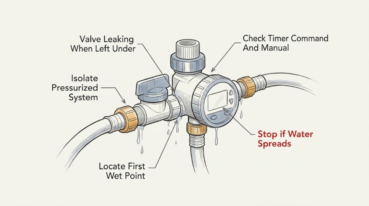
A valve or garden-timer assembly that leaks only while the supply stays pressurized needs to be isolated before anything is opened. Turn off the timer schedule and close the upstream hose-bib or irrigation shutoff if it is accessible; do not dismantle a valve under pressure. Find the first wet point: a threaded hose or timer connection suggests a gasket, alignment, or fitting issue; water from the timer body, bonnet, bleed screw, solenoid, or valve seam suggests a damaged body, seal, diaphragm, or manual-open condition; water downstream after the timer is off may be residual low-point drainage. Use the exact timer and valve pressure rating, because excessive pressure or freezing can damage a timer. If the leak continues with the supply isolated, the body is cracked, the valve will not close, the solenoid or diaphragm needs access, water is near an outlet, or the shutoff is inaccessible, leave the system off and arrange qualified irrigation or plumbing service.
Work through in order
Diagnostic checks
Use only checks that match the exact appliance or system and its official guide.
-
Check 1
Turn the garden timer schedule or manual run command off, keep clear of spray and wet electrical equipment, and close the upstream hose-bib or irrigation shutoff from a dry, stable position if one is accessible.
Expected result: The leak stops when the upstream supply is closed, continues from trapped downstream water, becomes a spray, or cannot be isolated because the shutoff is inaccessible or seized.
Next step: Leave the supply closed, mark the wet area, and wait for safe pressure relief from an appropriate downstream outlet without loosening the valve. Arrange plumbing service if isolation is unavailable or the leak is forceful.
Stop if: Do not loosen a bonnet, bleed screw, solenoid, hose, or threaded fitting while pressurized. Stop for flooding, a slippery surface, water near an electrical outlet, or a burst line.
Why this matters
Why: A leak that stops under isolation is pressure-dependent and can be inspected only after the assembly is safe. Continued flow may be residual drainage or a downstream supply issue; a forceful leak or unavailable shutoff is not a timer adjustment problem.
-
Check 2
With the supply isolated and the area safe, trace the water from the first wet point without wiping away the evidence: inspect the upstream threaded connection, timer body, valve bonnet or seam, bleed screw, solenoid, and downstream tubing or outlet.
Expected result: Water starts at a hose or timer thread, emerges from the timer or valve body, appears at a bonnet or solenoid seam, comes from a bleed point, or only exits downstream after the zone is off.
Next step: Photograph the first wet point and the timer and valve labels. Do not tighten multiple parts by guesswork or disassemble the assembly until the exact product instructions and pressure state are confirmed.
Stop if: Stop if the body is cracked, fittings are corroded, the assembly moves in the pipe, water reaches an electrical device, or the wet point cannot be identified without digging or opening the valve.
Why this matters
Why: A threaded wet point favors a gasket, cross-threading, or connection issue. A body crack, seam, bonnet, bleed, or solenoid wet point favors a seal or valve fault. Downstream-only flow can be residual low-point drainage, but continued flow under isolated supply requires further service diagnosis.
-
Check 3
With water still isolated, review the garden timer's current schedule, manual-run state, and exact instructions; inspect only the visible control or solenoid position and do not energize or remove a wired part.
Expected result: The timer is still commanding a zone, a manual-open control or solenoid appears engaged, the program is off but the valve remains open, or the control state is unknown.
Next step: Cancel the command according to the exact timer instructions and keep the upstream supply closed. Request qualified irrigation service when the valve remains open, the control state is uncertain, or any electrical testing would be needed.
Stop if: Do not open the timer enclosure, probe wires, apply power to a loose solenoid, or turn a manual bleed or solenoid under pressure.
Why this matters
Why: A controller command or manually opened solenoid can make a valve appear to leak or fail to close. A valve that remains open with the command off shifts suspicion toward debris at the diaphragm or seat, a damaged diaphragm, solenoid, wiring, or valve body.
-
Check 4
Read the timer and valve labels and installation documents, and record whether the leak began after a hose change, high-pressure event, freezing weather, winter storage, mainline work, or a new installation; do not exceed the product's stated pressure rating.
Expected result: The leak is at a threaded connection, the timer is outside its documented pressure or temperature conditions, freezing or thawing occurred, debris may have entered after line work, or no triggering event is known.
Next step: Keep the upstream supply closed and provide the labels, pressure-control information, weather history, and first wet point to a plumber or irrigation technician. Use only the exact product guidance for any connection inspection after pressure is relieved.
Stop if: Do not install an unverified pressure regulator, force a seized fitting, use heat to thaw the timer, or continue pressurizing equipment that is cracked, frozen, or leaking.
Why this matters
Why: A connection issue may be limited to a gasket or alignment, while pressure or freeze exposure can damage the timer body, diaphragm, solenoid, or fittings. Debris after installation or mainline work can prevent a diaphragm from seating. A missing history does not make the assembly safe to open.
-
Check 5
Only after the upstream supply is closed, pressure is safely relieved, the body is intact, and the exact product instructions permit it, inspect the visible gasket, O-ring, bleed screw, bonnet hardware, or hose washer without opening the valve chamber.
Expected result: A gasket or washer is visibly displaced or damaged, an external screw or solenoid is visibly loose, the body or seam is cracked, the diaphragm chamber is inaccessible, or no external defect is visible.
Next step: Replace or reseat only the exact external seal or user-serviceable item specified for the identified model, then restore the connection without cross-threading and test briefly while watching from a safe position. Use a plumber for any bonnet, diaphragm, solenoid wiring, pipe, or body work.
Stop if: Do not open a valve chamber, remove a diaphragm, disconnect wiring, use tools on a pressurized assembly, apply sealant where the manual does not specify it, or test a cracked body.
Why this matters
Why: A visible external seal or hand-tight component may explain a connection leak. A crack, inaccessible diaphragm, or clear external parts with continued leakage points toward replacement or internal diagnosis, not more tightening.
-
Check 6
After any permitted external correction, restore water from the upstream shutoff slowly and observe the timer, valve body, connections, and downstream outlets through one scheduled or manual cycle; stop the supply again at the first sign of leakage.
Expected result: The assembly stays dry with the timer off, leaks only when the timer commands flow, leaks while the valve should be closed, or begins leaking immediately when pressure returns.
Next step: Keep a leaking assembly isolated and arrange qualified plumbing or irrigation service. Report the exact valve and timer model, first wet point, command state, pressure or freeze history, and the result of the supervised observation.
Stop if: Do not repeat pressurization, leave the timer under pressure unattended, bypass a valve, or continue after a body crack, uncontrolled flow, electrical contact, or water damage.
Why this matters
Why: A dry assembly after a corrected connection supports an external seal or alignment issue. Leakage while commanded may reflect a normal flow-path fault or downstream fitting, while leakage with the command off points toward a valve-closing, diaphragm, solenoid, body, or pressure problem.
Use your observations
Decision map
Find the observation that best matches what you see, then follow the next safe action.
-
PATH 01Next step
What you see
After pressure is safely relieved, the first wet point is the hose, timer inlet or outlet, or another threaded connection, while the timer and valve body are intact.
Do this next
Follow the exact product instructions for the identified connection and replace only a confirmed matching seal if permitted. Repressurize briefly while supervised; keep the supply closed if the connection still leaks.
Why this path and its safety boundary
Why it matters: A gasket, washer, alignment, cross-threading, or connection issue is more likely than a failed diaphragm.
-
PATH 02Next step
What you see
Water emerges from the timer body, valve body, bonnet seam, bleed point, or solenoid area, or the body is cracked or visibly distorted.
Do this next
Keep the upstream supply closed and arrange qualified irrigation or plumbing service. Do not open the valve chamber or continue pressurizing a cracked assembly.
Why this path and its safety boundary
Why it matters: A damaged body, seal, diaphragm, solenoid, or manual-open component is more likely than a simple hose washer.
-
PATH 03Next step
What you see
The timer schedule and manual command are off, but the valve continues to pass water or a zone continues flowing while the upstream supply remains available.
Do this next
Isolate the supply and give the technician the command state and duration of flow. Do not remove the solenoid or bonnet while pressurized.
Why this path and its safety boundary
Why it matters: Debris at the diaphragm or seat, a damaged diaphragm, a loose manual bleed or solenoid, wiring, or insufficient product-specific closing conditions may be involved.
-
PATH 04Next step
What you see
Leakage began after a pressure event, operation outside the timer's documented rating, freezing, thawing, or winter storage with water inside.
Do this next
Keep the system isolated, do not heat or repeatedly pressurize it, and have the exact timer and valve assessed for safe replacement or repair.
Why this path and its safety boundary
Why it matters: Pressure or freeze damage to the timer body, connections, diaphragm, solenoid, or valve is more likely, even if the leak is currently small.
-
PATH 05Next step
What you see
The supply is isolated, the timer and valve body stay dry, and water exits only from a downstream low outlet before stopping as the line empties.
Do this next
Monitor from a safe position until the line stops, then keep the timer and valve protected from freezing and record whether water returns when pressure is restored. Ask a plumber to assess persistent flow or backflow.
Why this path and its safety boundary
Why it matters: Residual water or low-point drainage is more likely than a pressurized valve leak, but continued flow or a wet valve body changes the diagnosis.
Helpful context
Understand the symptom
A timer-off leak is not automatically a failed valve
A garden timer can stop its schedule while the faucet or irrigation shutoff still leaves the timer and valve under static pressure. A drip at a threaded connection, a wet timer body, a valve that remains open, and water that only drains from a low outlet are different observations. Locate the first wet point before choosing a gasket, timer, diaphragm, or complete valve.
Close the supply before relieving pressure or opening anything
Hunter warns that opening an irrigation valve under pressure can cause injury. Use an upstream shutoff, stop the timer program, and let a downstream outlet discharge only from a safe position. If no safe shutoff is available, the leak is forceful, or the assembly is attached to a building supply that cannot be isolated, stop and use a plumber rather than loosening a cap or solenoid.
Pressure and weather can turn a small leak into equipment damage
Orbit advises keeping a hose timer within its product pressure range and draining it before freezing weather; pressure outside the rating or frozen water can damage the body, connections, diaphragm, or solenoid. EPA irrigation guidance treats valves, pressure-regulating devices, and automatic controller-operated valves as system components that need the correct function and installation.
Safety boundary
Stop conditions
- Stop immediately for a forceful spray, flooding, a cracked or distorted body, water near an electrical outlet or controller, or a slippery or unstable work area.
- Close the upstream supply and do not open a valve, bonnet, bleed screw, solenoid, hose, or threaded fitting while the assembly is pressurized.
- Do not exceed the exact timer or valve pressure rating, heat frozen equipment, bypass a valve, probe controller wiring, or repeatedly pressurize a leaking assembly.
- Stop after one supervised restoration if the leak returns, the valve will not close, the body or seam leaks, or the issue requires pipe, diaphragm, solenoid, or pressure diagnosis; arrange qualified plumbing or irrigation service.
Only after diagnosis
Potential parts
- hose-timer washer or gasket
Consider this only when the leak starts at a threaded hose or timer connection, the timer and valve body are intact, and the exact product instructions identify a replaceable seal.
Confirm the exact timer model, connection type, and manufacturer fit information; do not substitute a seal based only on outside appearance. - irrigation valve diaphragm or solenoid seal
Consider this only after qualified diagnosis finds debris, a damaged diaphragm, or a solenoid seal problem in a valve that remains open or weeps with the timer command off and the supply path is clear.
Confirm the exact valve model, diaphragm orientation, solenoid type, and pressure conditions; internal valve work requires a fully isolated and safely depressurized system.
When checks do not resolve it
Need a professional?
Arrange qualified plumbing or irrigation service when the supply cannot be safely isolated, the valve or timer body leaks, the valve remains open with the timer command off, a diaphragm or solenoid must be accessed, the assembly has pressure or freeze damage, or a connection still leaks after a model-approved external seal check. Keep the garden timer and upstream supply off while awaiting service.
Common questions
FAQ
Why does my garden-timer valve leak only when it is left under pressure?
Static pressure can expose a weak gasket, connection, valve seal, diaphragm, solenoid, or cracked body even when the timer schedule is off. Close the upstream supply, locate the first wet point, and do not open the assembly while pressurized.
Should I turn off the faucet feeding a garden timer?
If the timer or irrigation installation is not designed to remain pressurized and the upstream shutoff is accessible, keeping the supply closed when the system is not supervised can limit water damage. Follow the exact timer and irrigation instructions, and use a plumber when the shutoff is inaccessible or leaking.
Is a leaking timer connection the same as a leaking valve body?
No. Water that starts at a threaded hose or timer connection may indicate a washer, alignment, or fitting issue. Water from the body, bonnet, bleed point, solenoid, or valve seam needs a different diagnosis and often professional service.
Can freezing or high pressure damage a garden timer?
Yes. Orbit warns that frozen water and pressure outside the timer's documented range can damage the body, connections, diaphragm, or solenoid. Isolate the system, do not heat or repeatedly pressurize damaged equipment, and have the exact model assessed.
Read the exact guide
Official sources
- Water is leaking from joints | One Outlet Single-Dial Hose Faucet Timer | Help CenterOrbit Irrigation · Orbit official hose-faucet timer guidance; exact timer model pressure and weather limits control.
- Valves - Valve Not ClosingHunter Industries · Hunter official irrigation-valve support; product pressure and access differ by valve model.
- WaterSense Resource Manual for Building WaterSense Labeled New HomesU.S. Environmental Protection Agency · EPA WaterSense technical reference for installed irrigation systems; it does not replace the exact valve or timer manual.
- Home MaintenanceU.S. Environmental Protection Agency · EPA WaterSense home-maintenance guidance; local plumbing rules and exact product instructions also apply.
- Valves - External Valve LeakHunter Industries · Hunter official irrigation-valve support; exact product instructions govern another manufacturer's timer or valve.
Community feedback
Share a repair observation
Share a plain-text repair observation. Accepted observations are published automatically; this page may take a moment to update.